 Introducing the DSC Q Series
 Introducing the DSC Q Series
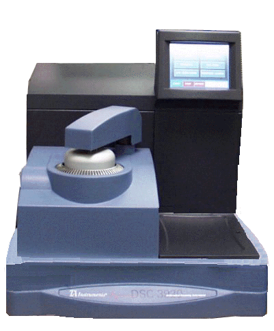 The Differential Scanning Calorimeter (DSC)
Q Series™
instruments determine the temperature and heat flow associated with material
transitions as a function of time and temperature. They provide quantitative
and qualitative data on endothermic (heat absorption) and exothermic (heat
evolution) processes of materials during physical transitions such as
phase changes, melting, oxidation, and decomposition. This
information helps the scientist or engineer identify processing and end-use
performance.
Select from the following topics for more information:


Differential scanning calorimetry (DSC) is a thermal analysis technique that measures the temperatures and heat flows associated with transitions in materials as a function of time and temperature. Such measurements provide qualitative and quantitative information about physical and chemical changes that involve endothermic or exothermic processes or changes in heat capacity. Typical measurements include:
Glass transitions in amorphous/semi-crystalline materials
Melting points; Boiling points
Crystallization time and temperature; Percent crystallinity
Heats of fusion and reactions
Oxidative stability
Purity
Rate of cure; Degree of cure
Reaction kinetics
Specific heat and heat capacity
Thermal stability
In a "heat flux" DSC, the sample material, encapsulated in a pan, and an empty reference pan sit on a thermoelectric disk surrounded by a furnace. As the temperature of the furnace is changed (usually by heating at a linear rate), heat is transferred to the sample and reference through the thermoelectric disk. The differential heat flow to the sample and reference is measured by area thermocouples using the thermal equivalent of Ohm's Law.
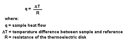
This simple relationship, however, does not take into account extraneous heat flow within the sensor or between the sensor and sample pan. The TA Instruments Q Series™ DSC's are specifically designed to account for those latter heat flows.
The cell sensor consists of a constantan body with separate raised platforms to hold the sample and reference. The platforms are connected to the heating block (base) by thin-walled tubes that create thermal resistances between the platforms and the base. Area detectors (thermocouples) on the underside of each platform measure the temperature of the sample and reference. A third thermocouple measures the temperature at the base. The equation below shows the thermal network model which represents this cell arrangement, and the resultant heat flow expression that describes this cell arrangement (designated the To [Tzero™] cell) is

The first term in this expression is the equivalent of the conventional single-term DSC heat flow expression. The second and third terms account for differences between the sample and reference resistances and capacitances respectively. These terms have their largest impact during regions of the thermal curve where the heat capacity of the sample is the predominant contributor to heat flow. The fourth term accounts for the difference in heating rate between the sample and reference. This term has its largest impact during enthalpic events (e.g., melting). This equation can be further modified to account for pan heat flow effects.
TA Instruments supplies the following Q Series™ DSC's.
The Q20/Q10 provides conventional (single-term) heat flow (commonly designated as "T1 heat flow") only.
The Q200/Q100 provides not only the single-term (T1) heat flow, but also the expanded four-term heat flow (designated as "T4 heat flow"), which accounts for the cell resistances and capacitances.
The Q2000/Q1000 provides T1 and T4 heat flows, as well as a third heat flow (designated as "TP4 heat flow"), which accounts for pan effects.
A working DSC system consists of three components—a DSC module (base and cell), a controller (computer with specific proprietary operation and data analysis software), and a cooling accessory. An Autosampler can be added to allow unattended evaluation of multiple samples, thereby increasing productivity. However, the Autosampler is optional and is not required to have a fully functional system.
The different components and accessories available with the different DSC Q series instruments are summarized in the table below.
For more information on components click on the desired topic:
|
DSC Q2000/Q1000 |
DSC Q200/Q100 |
DSC Q20/Q10 |
|
Touch Screen |
Touch Screen |
Keypad |
|
AutoLid I (standard on Q1000) AutoLid II (standard on Q2000, optional for Q1000) |
AutoLid I (standard on Q100) AutoLid II (standard on Q200, optional for Q100) |
Manual Lids (standard on Q10 and Q20) AutoLid II (standard on Q20 Auto model) |
|
Mass Flow Controller (MFC) (standard) |
Mass Flow Controller (MFC) (optional) |
Mass Flow Controller (MFC) (optional) |
|
Cooling Accessories: Finned Air Cooling System (FACS) Quench Cooler Liquid Nitrogen Cooling System (LNCS) Refrigerated Cooling System (RCS) |
Cooling Accessories: Finned Air Cooling System (FACS) Quench Cooler Liquid Nitrogen Cooling System (LNCS) Refrigerated Cooling System (RCS) |
Cooling Accessories: Finned Air Cooling System (FACS) Quench Cooler Refrigerated Cooling System (RCS) |
|
Autosampler: Standard |
Autosampler: Optional |
Autosampler: Not available for Q10. Optional for Q20. |
|
Available Cells: Standard cell Pressure cell (optional) |
Available Cell: Standard cell (hard-wired) |
Available Cell: Standard cell (hard-wired) |
|
Heat Flow Signals Available: T4P, T4, and T1 Standard and Advanced MDSC |
Heat Flow Signals Available: T4 and T1 Standard MDSC (optional) |
Heat Flow Signals Available: T1
|
|
Compatible with all pan types. |
Compatible with all pan types. |
High volume pans and high pressure pans cannot be used. |
The DSC Q20/Q10 and Q200/Q100 feature a "hard-wired" standard DSC cell that requires replacement by a trained serviceman. The DSC Q2000/Q1000 features an operator-replaceable standard DSC cell, as well as an optional high pressure DSC cell.
DSC Standard Cell
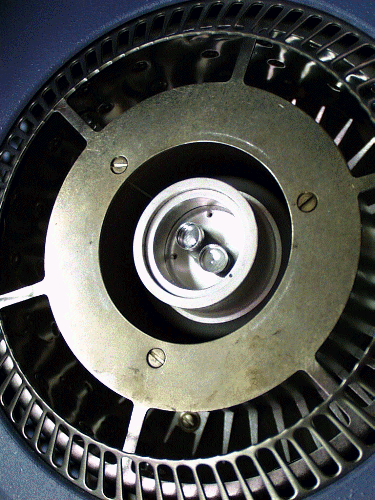 The standard DSC cell uses a constantan (thermoelectric)
sensor assembly as a primary heat flow element. A silver heating block,
covered with a pair of vented silver lids, encloses the sensor assembly.
The sample, contained in a sample pan, and an empty reference pan are
placed on the sensor platforms. Heat is transferred from the furnace through
the constantan sensor to both the sample and reference. Differential heat
flow to the sample and reference is monitored by CHROMELŪ-constantan area
thermocouples, formed by welding CHROMELŪ discs to the underside of the
constantan sensor platforms. The base of the sensor has a CHROMELŪ and
constantan thermocouple welded to its surface between the two platforms.
This Tzero thermocouple measures the temperature of the base of the sensor.
Sample temperature is determined by computing the DT
between the Tzero thermocouple and the sample thermocouple and adding
that difference to the Tzero temperature.
During experiments the cell is purged by a gas, which is preheated by circulation through the silver block before entry into the sample area. In addition, a base purge port circulates in the space below the cell to purge moisture from around the cell during cooling experiments with the RCS, LNCS, and Quench Cooler to prevent condensation. An air cool purge is used with the Finned Air Cooling System.
CHROMELŪ is a registered trademark of Hoskins Manufacturing Company.
DSC Pressure Cell
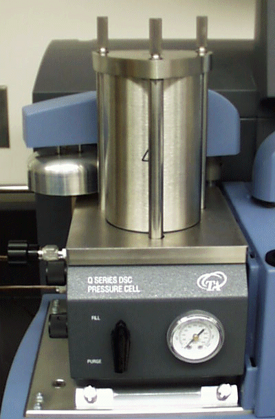 The Pressure
DSC (PDSC) cell (shown to the right) is a DSC cell enclosed in a steel
cylinder that can be pressurized to 7 MPa gauge (1000 psig). In addition
to performing most of the same basic measurements as the DSC cells, it
can operate at elevated pressure or under vacuum. This ability to vary
pressure as well as temperature provides the following:
Resolution of overlapping peaks
Determination of heats of vaporization and vapor pressure
Reaction rates in controlled atmospheres
Studies of pressure-sensitive reactions
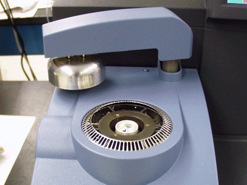
The AutoLid, or automatic arm and lid assembly is a standard feature on the DSC Q200/Q100 and Q2000/Q1000 models. The lid assembly is actually three lids in one. It contains the innermost silver lid, the cell cover, and the metal bell-shaped lid. When you touch the LID OPEN/CLOSE key on the touch screen, the arm will automatically move over the top of the cell and lower the lids into place.
The AutoLid comes in two types. AutoLid I was standard on the DSC Q1000 and Q100. AutoLid II is standard on the DSC Q2000, Q200, and Auto Q20, and is an optional upgrade for the DSC Q1000 and Q100.
See also:
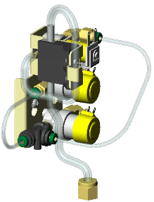 Accurate and precise control of purge gas is important
for obtaining good DSC results. A built-in Mass Flow Controller (MFC),
with gas-switching capability is available for the Q Series DSC's. Flow
rate is a selected parameter and the actual measured flow is automatically
stored with each data point. See
also: Recommended Purge
Gases and Flow Rates.