 Re-Aligning the AutoLidRe-Aligning the AutoLid
If your DSC is equipped with an automated lid mechanism, called the AutoLid, the positioning of this lid assembly is critical to the proper operation of the instrument. While the lid is carefully aligned before the instrument is shipped, you may find that with use the alignment of the AutoLid will need adjusting over time.
If your experiments begin to show problems with the baseline or with the Tzero calibration results, you may need to re-align the AutoLid.
Perform the following visual checks to determine if re-alignment is needed:
Select Control/Lid/Cycle Lid from the instrument control software. Observe the AutoLid as it closes. Watch the tube that supports the lid. As the lid closes the rod/tube should not be touching the sides of the bushing. If the rod/tube touches the sides or comes down at an angle, the AutoLid needs re-alignment.
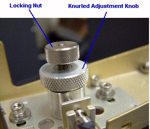
Remove the AutoLid arm cover (see procedure beginning in next section). Gently move the AutoLid arm and watch the locking nut (AutoLid II) or collet (AutoLid I) closely. See the figure below to identify the locking nut or collet. It should remain steady and not move with the arm. If the locking nut or collet moves, the AutoLid needs alignment.
Follow the instructions in the links below to perform the alignment.
There are some differences in the procedures depending on the type of AutoLid that you have installed on your instrument. The DSC Q1000/Q100 were shipped with AutoLid I. The DSC Q2000/Q200/Auto Q20 are shipped with AutoLid II. AutoLid II is also available as an upgrade for the Q1000/Q100.
You will need to know which type of AutoLid is installed on your instrument in order to perform the correct alignment procedure. To determine this, first follow the procedures below to remove the cover from the Autosampler arm. Once the AutoLid mechanism is exposed it will become obvious which type you have installed.
CAUTION: Make sure the cell has cooled to room temperature before beginning this procedure. Turn off all cooling accessories.
 Grasp the AutoLid arm cover on both sides and pull out the
sides enough to release the tabs holding it on. Tilt
the arm cover up from the back first then pull it up and towards you.
See the figures here.
Grasp the AutoLid arm cover on both sides and pull out the
sides enough to release the tabs holding it on. Tilt
the arm cover up from the back first then pull it up and towards you.
See the figures here.
Remove the cover.
Compare the pictures below to your particular AutoLid, if you are not certain which type you have. Follow the directions appropriate to the AutoLid installed on your instrument.
AutoLid II
AutoLid I
Follow these steps to re-align the AutoLid II (standard lid on the Q2000/Q200/Auto Q20). This procedure requires a delicate touch and attention to detail.
Remove the Autosampler arm cover as directed above.
Press the LID OPEN key on the Control Menu touch screen to open the AutoLid.
Remove the screws attaching the cell cover to the unit cover. Two screws are located on the side and one is located on the top. Retain the screws.
If your instrument has an Autosampler installed, lift up the cover to release the tabs and pull the cover towards you to remove it fully being careful not to damage the cell lids.
If you do not have an Autosampler, you will have to remove additional screws to release the cover. Then pull the cover towards you to remove it fully.
 Place one hand under the AutoLid assembly for support while
using the other hand to loosen the locking nut shown in the figure to
the right. This releases
the rod holding the inner and outer lids. The rod and two lids will drop
into your hand. You must be VERY careful when handling the silver lids
and tube because the metal is relatively soft and deforms easily.
Place one hand under the AutoLid assembly for support while
using the other hand to loosen the locking nut shown in the figure to
the right. This releases
the rod holding the inner and outer lids. The rod and two lids will drop
into your hand. You must be VERY careful when handling the silver lids
and tube because the metal is relatively soft and deforms easily.
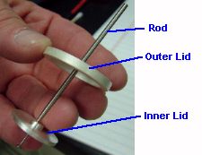
Place the inner/outer lids aside for now. The figure below shows the orientation of the two lids and the rod.
Obtain a 3/32-inch hexagon (Allen) wrench from the accessory kit.
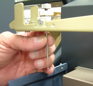
 Place one hand under the large insulating lid again. Use the
other hand to loosen and remove the three shoulder screws from the insulating
lid. The insulating lid will drop into your hand. Put the insulating lid
aside. See the figure to the right for the proper removal of the insulating
lid.
Place one hand under the large insulating lid again. Use the
other hand to loosen and remove the three shoulder screws from the insulating
lid. The insulating lid will drop into your hand. Put the insulating lid
aside. See the figure to the right for the proper removal of the insulating
lid.
Remove the two lids from the rod.
Place the inner lid into the DSC cell upside down (with the knob side down) and centered.
Orient the rod with the flared tip facing down. Slide it up from the underside of the arm into the center section of the AutoLid assembly. See the figure below. Continue to push the rod up until the rod protrudes at least 0.5 inches above the locking nut. Gently tighten the locking nut.
Press the LID CLOSE key on the Control Menu touch screen to close the AutoLid.
 Loosen the locking nut and slide the rod down toward the lid
until is close to, but not touching the lid. Gently tighten the locking
nut.
Loosen the locking nut and slide the rod down toward the lid
until is close to, but not touching the lid. Gently tighten the locking
nut.
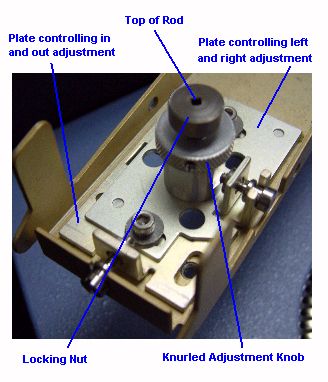
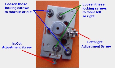
Slightly loosen all four sockethead locking screws on the AutoLid II assembly plates. See the figure to the right.
Confirm that the inner lid is still centered on the cell and is upside down.
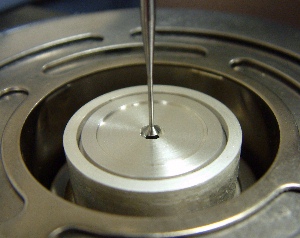
Using the adjustment screws move the AutoLid assembly plate front to back and left or right until the flared tip of the rod is centered over the hole in the inner lid as seen in the figure below.
Tighten all four sockethead locking screws to hold the assembly in place.
Loosen the locking nut and gently slide the rod down until the flared end rests on the inner lid at the bottom of the center recessed hole.
If the rod is not flush with the top of the locking nut, you will need to adjust the rod for height as directed in the next step.
Turn the knurled adjustment knob (located directly below the locking nut as seen in the bottom figure on page 3) clockwise to raise the rod or counterclockwise to lower the rod until it is flush with the top of the locking nut. When it is flush, gently tighten the locking nut.
Press the LID OPEN key on the Control Menu touch screen to open the AutoLid.
Loosen the locking nut and remove the rod by pulling it straight down.
 Obtain the three shoulder screws that were removed earlier.
Place them into their holes in the top of the arm. Holding the large insulating
lid in one hand, bring it up to the threaded part of the screws as seen
in the figure to the right.
Obtain the three shoulder screws that were removed earlier.
Place them into their holes in the top of the arm. Holding the large insulating
lid in one hand, bring it up to the threaded part of the screws as seen
in the figure to the right.
Using the 3/32-inch hexagonal (Allen) wrench, tighten the three shoulder screws while holding the insulating lid steady. Tighten the shoulder screws only until they bottom out. Do not over tighten.
Remove the inner lid from the cell and install the rod through the lid, making sure the recessed center of the lid is on the bottom as shown in the figure below. The flared tip of the rod will fit inside the recessed center.
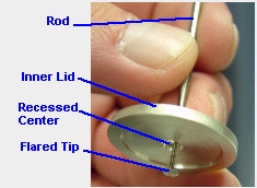
Obtain the outer lid. Orient the flat side of the outer lid so that it is at the top. Slide the outer lid over the rod so that it is on top of the inner lid. The inner lid will fit inside the recessed side of the outer lid.
Slide the rod, with two lids attached, up inside the AutoLid assembly until the top of the rod is flush with the top of the locking nut. Gently tighten the locking nut.
Select Control/Lid/Cycle Lid from the instrument control software to open and close the lid several times, observing to make sure the lid closes properly.
If the alignment does not meet the above criteria, repeat the alignment procedure.
Press the LID OPEN key on the Control Menu touch screen to open the lid.
Replace the unit cover and replace the screws.
Replace the arm cover.
The AutoLid II alignment should now be complete. If you have further difficulty with the AutoLid that this procedure does not address, call TA Instruments for service.
Follow these steps to re-align the AutoLid I (standard lid on the Q1000/Q100). This procedure requires a delicate touch and attention to detail.
Remove the Autosampler arm cover as directed above.
Press the LID OPEN/CLOSE key on the Control Menu options touch screen to open the AutoLid.
Remove the screws attaching the cell cover to the unit cover. Two screws are located on the side and one is located on the top. Retain the screws. If your instrument has an Autosampler installed, lift up the cover to release the tabs and pull the cover towards you to remove it fully being careful not to damage the cell lids. If you do not have an Autosampler, you will have to remove additional screws to release the cover. Then pull the cover towards you to remove it fully.
 Place one hand under the AutoLid assembly for support while
using the other hand to squeeze the clamp and pull the collet in an upward
direction. This releases
the tube holding the inner and outer lids. The tube and two lids will
drop into your hand. You must be VERY careful when handling the silver
lids and tube because the metal is relatively soft and deforms easily.
Place one hand under the AutoLid assembly for support while
using the other hand to squeeze the clamp and pull the collet in an upward
direction. This releases
the tube holding the inner and outer lids. The tube and two lids will
drop into your hand. You must be VERY careful when handling the silver
lids and tube because the metal is relatively soft and deforms easily.
Place the
clamp/collet assembly and inner/outer lids aside for now. The
figure below shows the orientation of the two lids and the tube.
Obtain a 3/32-inch hexagon (Allen) wrench from the accessory kit.
Place one hand under the large insulating lid again. Use the
other hand to loosen and remove the three shoulder screws from the insulating
lid. The insulating lid will drop into your hand. Put the insulating lid
aside. See the figure for the proper removal of the insulating lid.
Take the inner/outer lid assembly and slide the outer lid off the tube. You are now left with the inner lid and tube. Thread the tube up through the center bushing so that the tube extends up through the arm. DO NOT BEND THE TUBE.
Squeezing
the clamp on the collet/clamp assembly, install the collet on the tube
so that it now holds the inner lid as seen in the figure shown lower right.
Make sure
the top of the tube is flush with the surface of the collet—the tube should
not extend above the surface of the collet.
Press the LID OPEN/CLOSED key on the Control Menu options touch screen to close the lid.
Observe the position of the closed lid on the cell. The object of this alignment procedure is to position the lid in the center of the cell and ensure that the tube is also centered in the bushing on the arm. You will make adjustments in the next several steps based on the position of the lid and tube.
Using your fingers, manually move the lid so that it is centered in the cell.
Looking down at the top of the arm, observe the position of the tube. You will need to move the adjustment screw(s) in the direction needed to bring the tube into the center of the bushing.
Use a screwdriver to loosen the appropriate locking screws shown in the figure below depending upon whether you need to move the arm in the left/right direction or the in/out direction.
Use a screwdriver to now loosen or tighten the appropriate adjustment screw to move the tube in the desired direction. When the tube appears to be centered again, tighten down the locking screws to hold it in place.
CAUTION: Cradle the arm with the opposite hand when tightening the screws. Do not apply excessive pressure or over tighten the screws.
Press the LID OPEN/CLOSE key on the Control Menu options touch screen to open the lid, then press it again to close the lid.
Check the alignment for the following criteria:
The gap between the collet and the bushing should be no greater than 3.2 mm (1/8-inch) and no less than 1.6 mm (1/16-inch).
When you move the arm very slightly, the collet and tube should not move and should not be in contact with the bushing.
Back to top
If the alignment does not meet the above criteria, repeat steps 12 through 17 until it is properly aligned before proceeding with re-assembly.
Press the LID OPEN/CLOSE key on the Control Menu touch screen to open the lid.
Put your hand under the inner lid and squeeze the clamp again to release the lid. Place the clamp/collet and lid aside.
Obtain the three shoulder screws that were removed earlier. Place them into their holes in the top of the arm. Holding the large insulating lid in one hand, bring it up to the threaded part of the screws as seen in the figure here.
Using the 3/32-inch hexagonal (Allen) wrench, tighten the three shoulder screws while holding the insulating lid steady. Tighten the shoulder screws only until they bottom out. Do not over tighten.
Take inner lid and slide the outer lid over the tube to reassemble the lids. Then thread the tube up through the center bushing so that the tube extends up through the arm. DO NOT BEND THE TUBE.
Squeezing the clamp on the collet/clamp assembly, install the collet on the tube so that it now holds the inner/outer lid assembly in place. Make sure the top of the tube is flush with the surface of the collet—the tube should not extend above the surface of the collet.
Select Control/Lid/Cycle Lid from the menu to open and close the lid several times, observing to make sure the lid closes properly.
Check the alignment for the following criteria once again:
The gap between the collect and the bushing should be no greater than 1/8-inch (3.2 mm) and no less than 1/16-inch (1.6 mm).
When you move the arm very slightly, the collet and tube should not move and should not be in contact with the bushing.
If the alignment does not meet the above criteria, repeat the alignment procedure.
Press the LID OPEN/CLOSE key on the Control Menu touch screen to open the lid.
Replace the unit cover and replace the screws.
Replace the arm cover.
The AutoLid I re-alignment is now complete. If you are still experiencing problems with the AutoLid after performing this procedure, call TA Instruments for service.