Generating Mesh for 2D-DIC
Open the PreProcessor
Set the “Camera Mode” DropDown List to “Camera 1” (optional)
In the Image Panel , load the first image in the image sequence you want to analyze. Typically this is the image where the specimen has no deformation (Before the loading starts).
Only structured meshing is implemented in the software. However, functionalities for mesh generation using the Abaqus meshing tool is implemented. The following two sub-sections shows how both structured and non-structured meshing is carried out.
Structured Meshing
- Open the Mesh Generation Tool . From the menubar: Tools -> Mesh -> Mesh Generation.
- In the Mesh Generation Tool , click “Generate Structured Q4”.
A dialog box will appear:
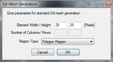
- Provide the desired element size of the mesh (or just accept the default values) and click “OK”.
An Action will be started in the Image Panel called “Define polygon to make new Q4 mesh”.
- Click in the image in the corresponding Image Panel to define a polygon surrounding the mesh to be generated.
The Action is confirmed by either clicking the “V”-button in the Action Panel, or by double-clicking when defining the last point of the polygon.
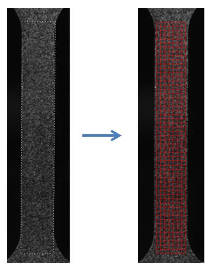
Below you see an example of the defined polygon (LEFT) and the corresponding mesh (RIGHT) that was generated:
You can modify the mesh using the tools in Mesh Edit Tool This toolbox supports Translation, Rotation, Scaling and more advanced mesh modifications (“Modify Mesh Q4” or “Modify Mesh Q8”). You can also select and delete elements if you want, using Mesh Edit Tool.
Note
The mesh should not be larger than the specimen, such that parts of the mesh is outside the region of the specimen in the image.
This will most likely cause problems with the DIC analysis.
When you are happy with how the mesh looks, you can save the mesh:

You are now done making the mesh for a 2D-DIC analysis.
Remember where you saved the mesh file (*.ecm) and close the PreProcessor
Non-Structured Meshing using Abaqus
To use this feature, Abaqus has to be installed on your computer.
It is assumed that you have opened an image of an unloaded specimen in the PreProcessor.
The image below shows a specimen with a circular hole in the middle. If you want to make the mesh cover the specimen surface all the way to the circular boundary, this is not possible using structured meshing.

- Open the Path Tool . From the menubar: Tools -> Paths.
- Click “Define New Path”. We want to define the outer boundary of our non-structured mesh
An action called “Define path” is now active.
- Click in the image to define the outer boundary of the mesh.
Hint
The “Zoom In” and “Drag Image” actions can be used without exiting the “Define path” action.