Make and Run 3D-DIC Input File
It is assumed that you already have made the two meshes needed for a 3D-DIC analysis (see: Generating Mesh for 3D-DIC), and saved the meshes as a files (*.ecm).
Further, it is assumed that you have calibrated both cameras (see: Calibrate Cameras for 3D-DIC).
- In the Main Window right-click on the “DIC”-node in the Workspace Tree and click “New Empty Input File”.

the DIC Input File Editor will open:

- Click the “Add New Camera” button. A “Camera 2” node will appear in the tree structure at the left of the DIC Input File Editor.
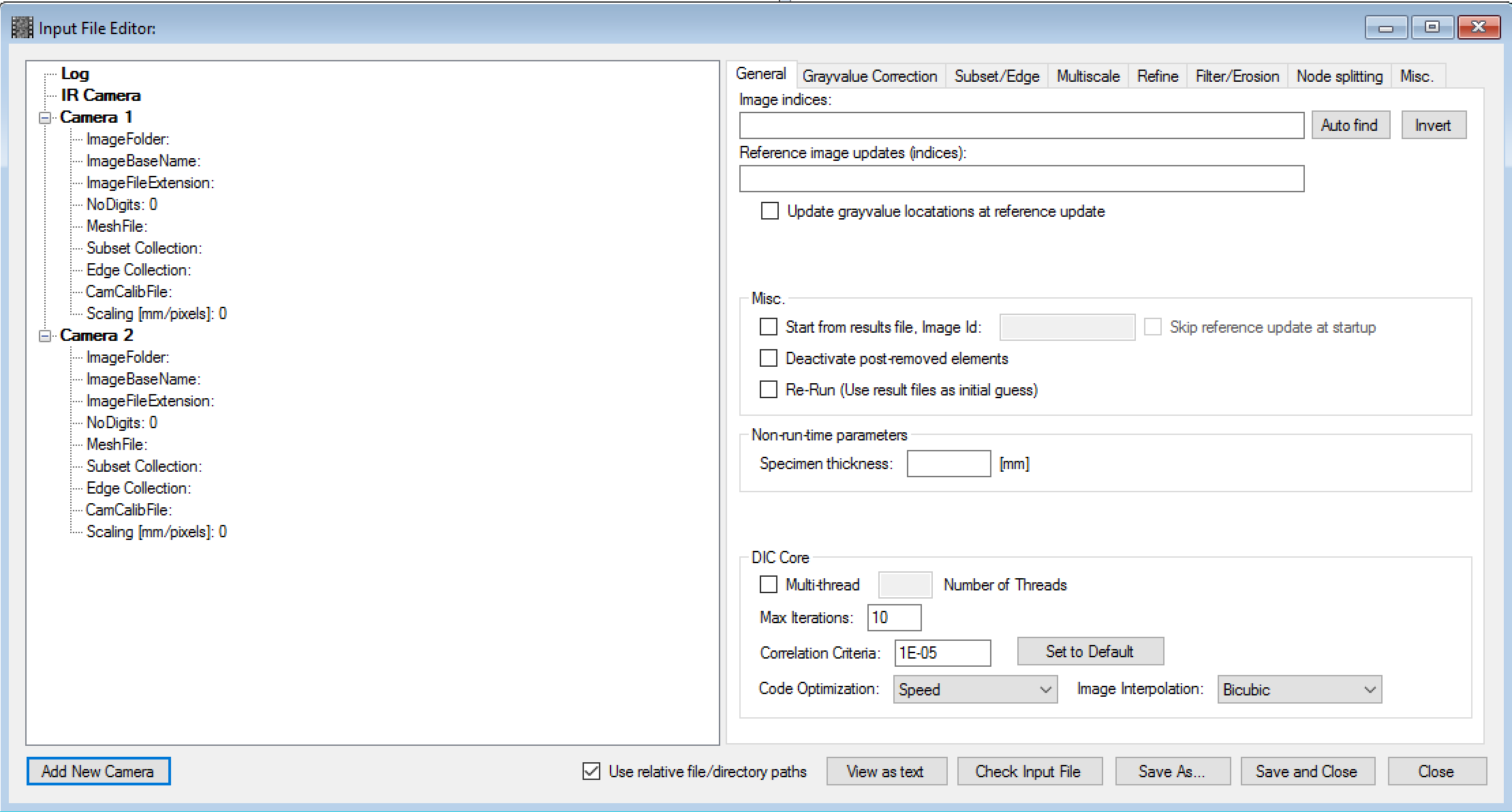
- Right-click at the “Image Folder” node under “Camera 1” and choose “Browse Image Folder...”. Select the image folder for camera 1.
Image base name, extension and number of digits should be filled out automatically.
- Do the same for the Camera 2 node.
- Click the “Auto Find” button at the right side of the DIC Input File Editor.
The indices of the common images in the two camera folders should be listed under the “Image indices” label.
- You can now add the two mesh files ( *.ecm ) and the two camera calibration files ( *.ecc ) to Camera 1 and 2 by right-clicking the nodes in the tree structure and browsing for the files.
Further, you may (or may not) want to:
- Add a log file (synchronized recordings of force, displacement, etc...)
- Use multi-thread (to reduce the computational time)
- Use relative paths (makes it easier to copy result files between different locations and computers)
- Use reference image updates (to account for e.g. large displacement gradients)
- Use grayvalue normalization (in cases of high degree of light variations)
- Use multi-scale coarse search (in cases of large displacements between images)
When you are done, you can press the “Save and Close” button.
Note
All results files from a DIC analysis will be saved in the same folder as the corresponding DIC input file! There will be as many results files as there are images defined in the input file.
Thus, to have control over different analyses, make a new folder each time you create and save a new input file. Preferable a sub-folder under the folder where the images are located (Example: C:/[Image Folder]/dic1/input.txt)
When the DIC Input File Editor has closed, you will see the input file as a node in the Workspace Tree under the “DIC” node:
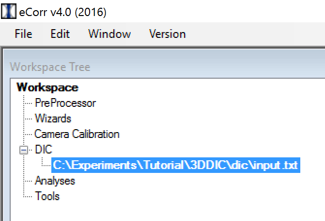
To run the DIC analysis, right-click on the input file in the Workspace Tree and press “Run” -> “DIC”.

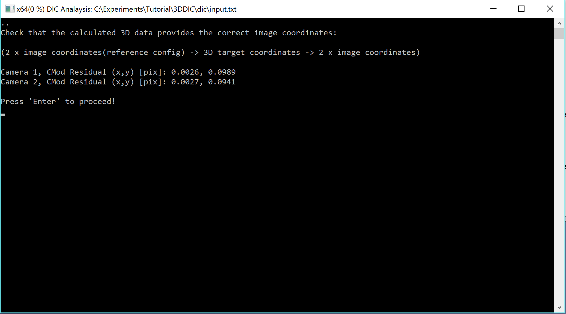
A console application ( DICCore.exe ) will appear. For a 3D-DIC analysis, some residuals from the camera models are reported (TODO). Press “Enter” to start the 3D-DIC analysis.
Note
If the console application do not appear, and you get a dialogbox saying “Cannot start 2D-DIC process”, go to menubar: Edit -> Settings, choose the “Analysis” tab. The path labelled “DIC Core Folder” should point to the location of the “DICCore.exe” file. This is normally located in a folder named “core”. Browse and find this folder. Click “Apply” to close the “Settings Window”. Now you can try running the DIC input file as described above.
You can now study the progress of the 3D-DIC analysis in the console window:

Now, if the DIC analysis is running, you can go straight to Study Results for 3D-DIC. It is possible to study the results even if the analysis is running. However, there will be missing results until the DIC analysis is done.
Note
If you want to access the input file or the DIC results after you have closed and restarted eCorr, you can reload the input file from the menu that appears when right-clicking the “DIC” node in Workspace Tree , and choose “Load Input File”. The inputfile is used to access the results from the DIC analysis, as is shown in Study Results for 3D-DIC.