DIC Input File Editor
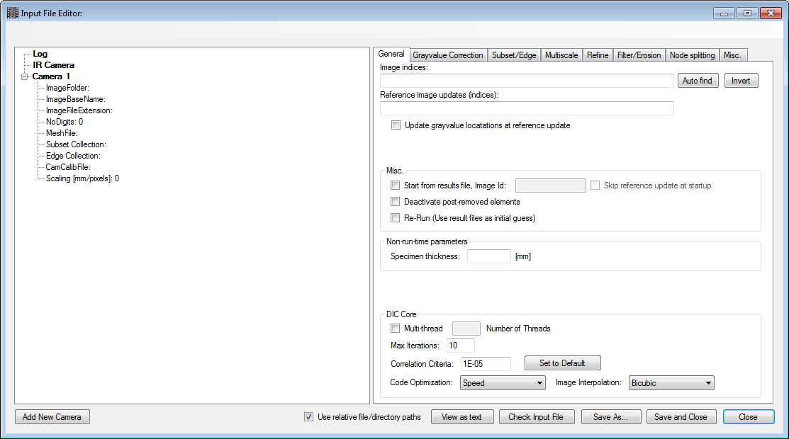
The DIC Input File Editor is used to specify the input parameters for a particular analysis. Input files for 2D-DIC, 3D-DIC, Point Tracking or Edge Tracing may be edited using this editor.
Hint
To start edit an empty input file, right-click the DIC-node in the Workspace Tree, and select New Empty Input File.
Hint
To edit an existing input file, first open the input file (Workspace Tree ⟶ right-click DIC node ⟶ Load Input File...). Optionally, you may drag-and-drop the file form the Windows File Explorer into the Workspace Tree. The path of the input file will make a new sub-node under the DIC node. Right-click this sub-node and click Input File Editor.
Add Image Folder
- Right-click on the “Image Folder”-node under “Camera 1” and select “Brose image folder...”.

A dialogbox will appear with information on how many images was found in the folder. Also, the ImageBaseName-, ImageFileExtension- and NoDigits-nodes wil be automatically filled out, based on the found images in the specified folder.
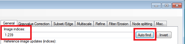
- Click the Auto Find-button to include all found images in the image folder to the analysis.
The “Image Indices”-textbox will be filled with all images found in the folder. This textbox may be manually edited, if you choose not to analyze all images. Here are some information on how the image indices format is defined.
Add a Log-File
- Right-click the “Log”-node int the top-left corner, and select “Brose for log file...”.
- Choose the assoicated log file (typically containing force, displacement, etc...).
Note: The log file does not affect the analysis. Thus, the log file may be added at any point, even after the analysis is finished.
Add a Mesh for Standard DIC
- Right-click on the “Mesh”-node under “Camera 1” and select “Brose mesh file...”.
- Choose the mesh file (*.ecm) you want to use for Camera 1.
Add a Subset Collection for Subset-DIC
- Right-click on the “Subset Collection”-node under “Camera 1” and select “Brose subset collection file...”.
- Choose the subset collection file (*.scol) you want to use for Camera 1.
Add an Edge Collection for Edge-Tracing
- Right-click on the “Edge Collection”-node under “Camera 1” and select “Brose edge collection file...”.
- Choose the edge collection file (*.ecol) you want to use for Camera 1.
Add a Camera Model (3D-DIC only)
- Right-click on the “CamCalibFile”-node under the “Camera”-node and select “Brose camera calibration file...”.
- Choose the camera model file (*.cmod) you want to use for this Camera.
Set a Per-Camera MM-to-Pixel Scaling Factor
- Right-click on the “Scaling [mm/pixel]”-node under the “Camera”-node and select “Set Image Scaling...”.
A dialogbox appears that let you define a spesific mm-per-pixel scaling for the particular camera.
Note: The mm-per-pixel scaling does not affect the analysis. Thus, the scaling may be added at any point, even after the analysis is finished.
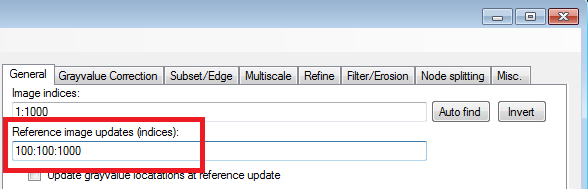
Add Reference Updates to the DIC Analysis
- Under the “Reference Image Updates”-textbox, spesify the image indices where reference updates should be performed.
In the example below a reference update is carried out for every 100th image. See here for information on the image indices format.
Start From a Results File
- Check the “Start from results file”-checkbox and specify the image index of the results file to start from.
Make sure that the spesified results file exist!

Hint
When starting from a results file, a resference update is by default added to the DIC analysis. Check the “Skip reference update...”-checkbox to prevent a reference update at startup.
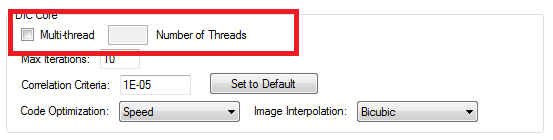
Running a Multi-Threaded analysis
- Check the “Multi-thread”-checkbox and specify how many threads the analysis should be distributed to.
Note
The maxmimum number of threads are 10, and for a proper speed-up of the analysis, the number of threads should not exceed the number of physcial cores on your CPU.
Specifying DIC Correlation Parameters
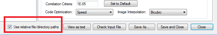
- The default settings for the correlation parameters are:
- Maximum Iterations = 10
- Correlation Criteria = 1e-5
The default parameters works well for most cases, but may also be edited by the user.

Using Relative Paths
By default the input files are stored with relative paths. This means that the path to the images, mesh files, subset collections, camera models, etc... are given as paths relative to the path of the input file. This makes it easier to copy the entire set of files and subfolders containing images and results files between different locations, hard drives, etc...
If the “Use relative file/directory paths”-checkbox is un-checked, all paths will be given as absolute paths in the input file.
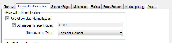
Adding Grayvalue Normalization
- Under the “Grayvalue Correction”-tab check the “Use Grayvalue Normalization”-checkbox
- If all images should be analyzed with this normalization, check the “All Image”-checkbox, or specify the image indices where this feature should be active.
- Choose “Normalization Type”: Constant Element. The other types are more or less experimental.
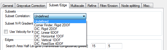
Specifying Subset DIC Optimization Type
Subset collections can be tracked using essentially two different optimization algorithms, i.e. DIC and Corner Finder.
The “Corner Finder”-algorithm tries to position the subset in the center of a checkerboard corner, i.e. the intersection bewteen two black and two white squares.
The “DIC”-algorithm, on the other hand, correlates the subset in a current image against a reference subset in a reference image by matching the underlying grayvalues. Different subset degrees-of-freedom (DOF) may be used. The standard is here a Linear Subset with 6 degrees of freedom (center point displacement + displacement gradient), but Rigid Subsets with 2 degrees of freedom may also be used if negligible specimen deformation can be assumed.
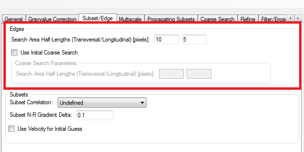
Settings for Edge-Trace Analysis
The settings for an edge-trace analysis are specified under the Subset/Edge tab.
The settings are very basic, and only contains the size of a calculation region, i.e. the size transversal to edge edge, and longitudinal to the edge. The default settings are 10 pixels transversal to the edge and 5 pixels longitudinal to the edge. By increasing the transversal size, the analysis may become more robust and allow larger jumps between succeeding images, while by increasing the longitudinal size the edge is ‘smoothed’.
Adding Multiscale DIC (Coarse-Search)
This feature is only implemented for standard DIC (not Subset-DIC), and is essentially a coarse search routine that is carried out before the standard (and fine-search) DIC. It may be used in cases where there are too large displacement increments (jumps) between two succeeding images in a DIC analysis. The standard DIC assumes relative small nodal displacement increments for each image in an analysis. If the displacement increments are sufficiently large, the standard DIC-algorithm fails. The “Multiscale”-feature helps by providing an initial guess for the nodal displacements, that are closer to the actual set of nodal displacements.
The multiscale approach are carried out in steps. There are room for 9 steps, but typically only 1 to 4 steps are nessesary.
Each steps is defined by a low-pass filter degree (which filters the underlying images used for correlation) and an optimization type.
- The optimization types available are:
- Rigid Body (2 degrees of freedom): The mesh is correlated assuming the entire mesh is rigid, i.e. the mesh is moved horizontally and vertically in the image
- Super Q4 (8 degrees of freedom): The mesh is correlated assuming the entire mesh to be a large Q4 element.
- Super Q8 (16 degrees of freedom): The mesh is correlated assuming the entire mesh to be a large Q8 element.
The low-pass filter is based on a two-dimensional FFT-algorithm. An increased mask size gives decreased level of low-pass filtering and the range is 1 to 500.
The main idea here, is to increse the level of details in the image, while increasing the degrees-of-freedom in the correlation.

Hint
The multiscale alogorithm can be manually (and visually) tested using the DIC Tool.