Installing the Pressure CellInstalling the Pressure Cell
To install the DSC Pressure (PDSC) Cell, follow these instructions and refer to the accompanying figures.
CAUTION: Do not remove the white, fibrous insulation from inside the cell cover. Refer to the MSDS sheet supplied with the Pressure DSC Cell for the necessary precautions.
Follow these steps to install the pressure cell on the Q2000/Q1000:
Follow these steps to install a pressure cell on the Q20P/Q10P:

To remove the DSC Q2000/Q1000 standard cell from the instrument before installing the Pressure DSC cell, follow these steps:
Select the Control/Lid/Open function to raise the AutoLid from the Q2000/Q1000 cell and cause it to move out of the way to its home position. If the Q2000/Q1000 is equipped with an Autosampler, press the HOME key on the Autosampler touch screen to move it to the "home" position.
NOTE: The Pressure DSC cell is not compatible with the DSC Q2000/Q1000 AutoLid or Autosampler. These items must be disabled so that they remain out of the way (parked) during pressure cell experiments. The Q2000/Q1000 software automatically recognizes when a Pressure DSC cell is mounted and disables these two items.
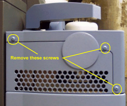
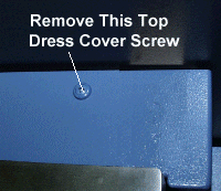
Pull the plug on the side of the unit cover out to remove it. Then remove the Phillips head screws attaching the cell cover to the unit cover. Three screws are located on the side and one is located on the top. Retain the screws.
If your instrument has an Autosampler installed, lift up the cover to release the tabs and pull the cover towards you to remove it fully. If you do not have an Autosampler, you will have to remove additional screws to release the cover. Then pull the cover towards you to remove it fully.
If there is a cooling accessory installed, make sure that is has reached room temperature, then remove it. For instructions on removing a cooling accessory, reverse the instructions for installing the cooling accessory. See also: Installing a Quench Cooler, Installing the Finned Air Cooling System, Installing the LNCS, Installing the RCS.
Remove the two thumbscrews at the front of the cell base as shown in the figure to the right.
Make sure the cell has reached room temperature, then slide out the cell.
Install the PDSC cell on the Q2000/Q1000 as instructed in "Installing the PDSC Cell (Q2000/Q1000 or Q20P/Q10P)," then install the dress cover as directed in "Installing the Cell Dress Cover on the Pressure Cell (Q2000/Q1000 or Q20P/Q10P)."
The TA Instruments Q20P/Q10P is a dedicated pressure DSC system. However, it has been designed so that the operator can readily replace an old (damaged, nonfunctional) Pressure DSC cell with a new one, should the need arise. This replacement is accomplished by removing the cell dress covers and old cell as described in this section and then installing a new cell as described in Installing the PDSC Cell (Q2000/Q1000 or Q20P/Q10P).
Follow these directions:
 Use a Phillips head screwdriver to remove the single screw
holding the top piece of the cell dress cover in place behind the cell
(shown to the right).
Use a Phillips head screwdriver to remove the single screw
holding the top piece of the cell dress cover in place behind the cell
(shown to the right).
Slide the top piece up and remove it.
Slide the bottom piece of the cell dress cover out and remove it as shown in the figure below.
Make sure that the cell is at ambient pressure (i.e., is not pressurized). Disconnect all tubing from the IN and OUT ports.
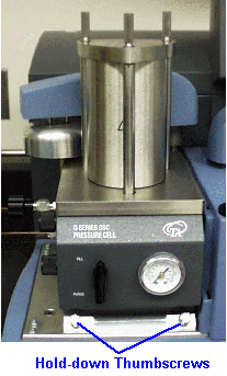
Remove the two thumbscrews at the front of the cell base.
Make sure the cell is at room temperature. Then slide out the cell.
Install the new PDSC cell as directed below.
Hold the PDSC and slide it onto the baseplate. The back of the cell should touch the connector housing on the DSC base.
 Install the two hold-down thumbscrews, then turn them clockwise.
The hold-down
screws need only be finger tight to keep the PDSC stable.
Install the two hold-down thumbscrews, then turn them clockwise.
The hold-down
screws need only be finger tight to keep the PDSC stable.
Connect a sufficient length of 0.125-inch tubing from a pressure regulator on your pressurized gas source to the IN port on the side of the PDSC Cell as shown to the right. The gas (nitrogen, air, oxygen, argon, etc.) should be pressure-regulated up to 7 MPa gauge (1000 psig).
WARNING: If hydrogen is used, the Pressure DSC cell must be filled in a way that ensures no oxygen is present at elevated temperatures.
CAUTION: If oxygen is used, be certain to use fittings, gauges, and tubing that are oxygen-rated.
The regulator you choose should have two gauges: one to monitor source pressure and one to monitor the regulator output pressure. The regulator should be rated to withstand the source pressure; its output should cover the experimental range up to 7 MPa gauge (1000 psig).
WARNING: DO NOT connect the PDSC directly to a pressurized gas source without using an appropriate regulator.
WARNING: The tubing must be of sufficient strength to withstand the pressure to be used in your experiments.
Install the cell cover as directed in Installing the Cell Dress Cover on the Pressure Cell (Q2000/Q1000 or Q20P/Q10P), then calibrate the Pressure DSC cell after installation. See Calibrating the DSC Pressure Cell.
A special dress cover for the pressure cell can be placed on the cell after the PDSC cell is installed as directed earlier in this chapter. The dress covers used for the Q20P/Q10P are slightly different from that used for the Q2000/Q1000. The Q2000/Q1000 dress cover is modified to accommodate the presence of the AutoLid and Autosampler on the Q2000/Q1000. However both dress cover types can be installed following the same procedures below. (The Q20P/Q10P is shown in the figures.)
Slide the bottom piece of the cell dress cover onto the cell
base as shown in the figure to the right. Push
it back until it touches the back of the unit.
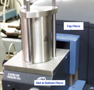
Slide the top piece down over the cell connector as seen in the figure below and match up the tabs in the top piece with the slots in bottom piece.
Use a Phillips head screwdriver to install the single screw holding the top piece of the cell dress cover in place.
![]()