 Installing the LNCSInstalling the LNCS
Click on one of the following topics for the procedures used to install the Liquid Nitrogen Cooling System:

Ice and frost are created during normal use of the Liquid Nitrogen Cooling System (LNCS). The catch trough is designed to prevent water from dripping onto the floor creating a potential hazard when the ice and frost melt.
 The catch trough is installed as follows:
Using a 5/8-inch wrench on the brass fitting, screw the plastic valve into the fitting until it is hand tight with the handle facing out.
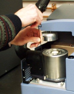
Slip the catch trough down over the tank. Move the catch trough down as low as possible on the tank as shown in the figure to the right.
Place the stainless steel band clamp over the inside edge of the trough using the molded lip as an alignment guide. Tighten the clamp with a screwdriver to seal the trough to the tank. Do not over tighten the clamp.
The trough can be emptied periodically by opening the valve and draining the water into a suitable container, or a hose can be connected to the valve and routed to a floor drain or large container.
CAUTION: During manual filling operations, do not over fill the LNCS tank causing liquid nitrogen to spill into the catch trough. Excessive amounts of LN2 will cause the catch trough to become brittle and shatter.
Follow the instructions below to install the cooling head:
Remove the lid(s). You can either manually remove the lids or select the Control/Lid/Open function to raise the AutoLid from the cell and cause it to move out of the way.
Pull the
plug on the side of the unit cover out to remove it. Remove the screws
attaching the cell cover to the unit cover, then remove the cover. See
Removing the Cell Cover for details.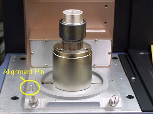
If the heat exchanger hose is already attached to the LNCS dewar, you will need to loosen the supply and exhaust fittings before mounting the cooling head on the DSC cell. Refer to Connecting the LNCS Lines for guidance, if needed. This allows the hose to rotate freely when positioning the cooling head in the steps to follow.
Align the pin on the cell base (shown here) with the corresponding slot in the LNCS Cooling Head. Carefully lower the head over the cell and make sure it is fully seated.
Obtain a long 3/32-inch hexagonal (Allen) wrench from the accessory kit.
Insert the tip of the wrench into any one of the three captive screws in the LNCS plate while holding onto the cooling head. (See the figure below.) DO NOT fully tighten yet.
Repeat step 6 for the two remaining captive screws. After you have started each screw, go back and tighten down all three screws until you feel them touch the bottom. Do not over tighten.
Slide the cover back over the cell and replace the screws removed in step 2. Push the plug back into place on the side of the cover.
Obtain access to the back of the LNCS and the back of the instrument.
Locate the
interconnect cable. Plug
one end of the cable into the 15-pin D instrument connector on the LNCS.
Plug the
opposite end of the cable into the port labeled COM2 on the back of the
DSC instrument (see the figure below).
Make sure that the large hose is not sharply bent or folded. It should curve gently between the instrument and the LNCS.
If you loosened the supply and exhaust fittings in step 3 above to allow the hose to rotate freely, retighten those fittings now.
Check the AutoLid alignment and adjust, if needed. See Aligning the AutoLid for the procedure.
Connect the cell base purge and the cooling gas (LNCS) purge lines, if you have not already connected them to the instrument.
After you have mounted the cooling head (also called the heat exchanger) on the DSC cell, follow these instructions to connect the supply and exhaust lines:
Loosen the captive screws on either side of the top cover of the liquid delivery tower. Pull the cover straight up to remove it.
 Obtain the 1.8-m (6-foot) long feed hose with its attached
cooling head. At
the opposite end from the cooling head are two lines that need to be connected
to the LNCS liquid delivery tower. The figure to the right identifies
the two lines that will be attached.
Obtain the 1.8-m (6-foot) long feed hose with its attached
cooling head. At
the opposite end from the cooling head are two lines that need to be connected
to the LNCS liquid delivery tower. The figure to the right identifies
the two lines that will be attached.
Using a 9/16-inch wrench attach the smaller liquid delivery line to the smaller fitting as shown in the figure below.
Using an 11/16-inch wrench attach the larger exhaust return line to the remaining fitting as shown in the figure above.
Replace the top cover over the liquid delivery tower.
Screw in the captive screws on the sides of the cover until they bottom out (finger tight).
Connect the 8-pin DIN cooling head connector to the port on the back of the LNCS electronics control box. See the figure below for the location of the connectors.
Connect the tank level BNC connector from the liquid delivery tower to the electronic control box, if it is not already in place.
Connect the 15-pin D connector cable to the instrument port on the LNCS electronic control box. The opposite end will go to the COM 2 port on the back of the DSC.
NOTE: A <HAR>-marked (harmonized) power cable meeting the standards of the country of installation is required for the European Economic Area.
Plug the power cord into the electronic control box and into the power outlet.
Toggle the power switch on the back of the LNCS electronics control box to ON.
Connect the house nitrogen gas to the nitrogen gas supply hookup, as shown in the figure to the right, if the LNCS is to be pressurized externally. Turn the black handle to the left (towards the nitrogen gas supply hookup) for external dewar pressurization. The supply line, a 50 to 70 kPa gauge (8 to 10 psig) nitrogen source, is used to control the operating pressure of the dewar to force LN2 into the heat exchanger.
WARNING: Do not use compressed air to pressurize the LNCS. Large amounts of liquid oxygen could accumulate in the dewar, creating a safety hazard.
.
If you want
to use internal dewar pressurization, turn the black knob to the right,
as shown in the figure. No
supply line needs to be connected.
Connect the cell base purge and the cooling gas (LNCS) purge lines, if you have not already connected them to the instrument.
You are now ready to fill the LNCS with liquid nitrogen. See Filling the LNCS for directions.