350a Analytical Model of Concentration Boundaries in Single Interface Isotachophoresis
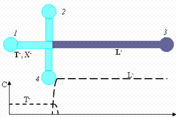
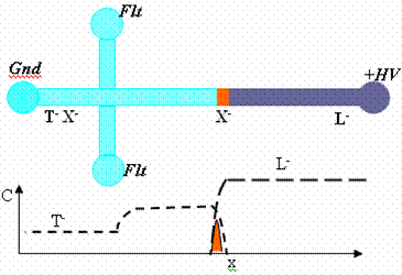
Single interface isotachophoresis has been used as a preconcentration technique to achieve up to million fold increase in sample concentration [1]. It employs an electrolyte system in which the mobility of the sample analytes is bound by mobility of the leading (LE) and the trailing electrolytes (TE). The sample ions are mixed uniformly in the trailing electrolyte, and not injected as a finite plug between the LE and TE as in conventional isotachophoresis. An initial interface between the LE and TE is created in simple-cross microchip geometry as illustrated in Fig 1. On applying an electric field, a steady diffused boundary forms at the LE and TE interface [2]. The sample ions in the TE overspeed trailing ions and accumulate in this moving concentration boundary [3].
The typical concentration of LE in the experiments is approximately 1 M and analyte concentration is 1 nM or less. The thickness of the diffused boundary is few microns and the channel length is order 10 cm. So, the concentration and length scale ratios involved in this problem are respectively order 109 and 104 or greater. This makes the problem numerically stiff and difficult to resolve fully. We present a simplified theoretical model to predict sample concentration growth and the characteristics of the moving concentration boundary. We perform controlled experiments to validate the theoretical model. The effects of varying current, leading and trailing ion concentration on the same concentration and moving boundary are investigated experimentally and compared with the theoretical model. The model is useful for experiment design and optimization of stacking and separation conditions.
Reference:
[1] Jung B, Bharadwaj R,
[2] Saville DA, Palusinki OA, AICHE Journal, 1986, 32, 207-214.
[3] Ludmila K,Bocek P, J. Chromatography, 1997, 689, 13-24.
|
|
|
| Fig. 1. Schematic of the distribution the leading (L-), trailing (T-) and sample (X-) ions ions at t = 0 and later instant after applying the voltage in the wells. The sample ions stack in the moving diffused boundary between the leading and trailing electrolyte. | |
|
|
| Fig 2. Experimental visualization of concentrated sample plug (Alexa Fluor 488) formed between the leading ion (Cl-) and trailing ion (Hepes-). |


