TMM4175 Polymer Composites
CASE STUDY: Free edge effects of laminates
Consider a specimen of a laminate with the layup [0/90/90/0] where the layer thickness is 1 mm and the total thickness is 4 mm. The width of the specimen is 20 mm. A tensile loading shall be imposed along the x-axis, and the detailed stress field far from the ends (i.e., at the middle of the specimen) shall be studied.
Due to the symmetry, it is sufficient to model only 1/4 of the y-z cross section when applying boundary conditions consistent with the symmetry condition. Furthermore, we can reasonably assume the stress field is uniform along the x-axis in regions far from the ends. That is, no gradients in the x-direction and therefore, only one element along this direction is needed.
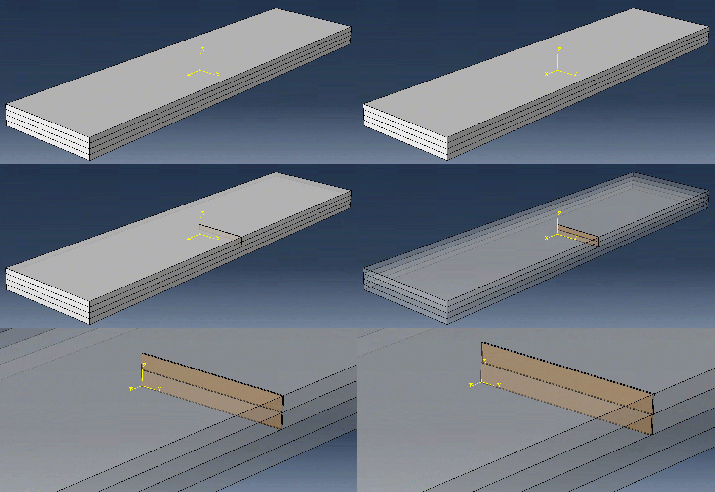
For symmetry conditions to be true, the model must have symmetry with respect to loading, geometry AND material. For example, a laminate of type [-45/45/45/-45] cannot be modelled with the assumption of symmetry about the x-z plane.
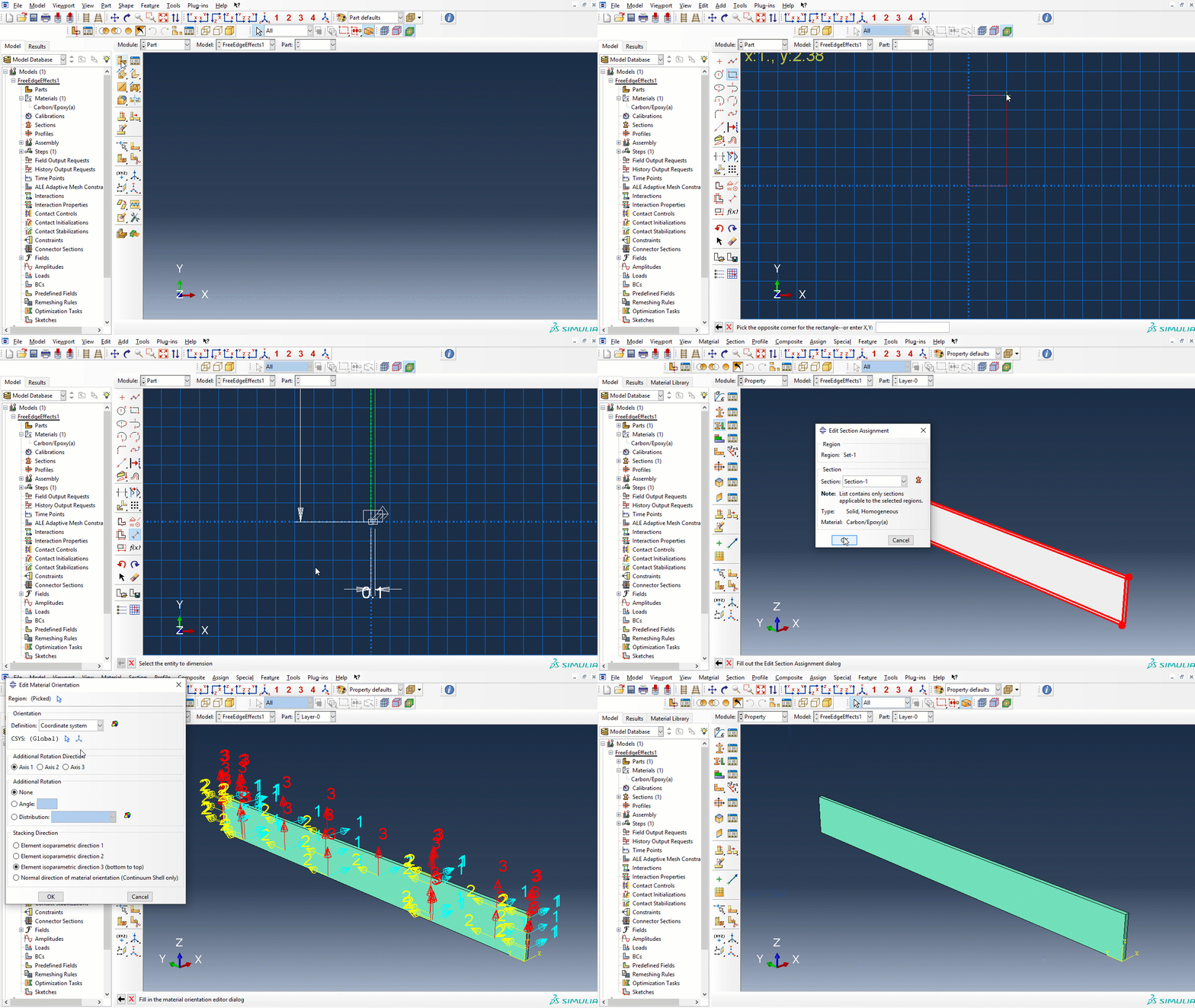
The model shall consist of two layers, one 0-oriented layer and one 90-oriented layer, both having a thickness of 1 mm and a width equal to 10 mm which is half of the total width. Ten elements through the thickness of one layer is a reasonable resolution for this problem, which suggest that the x-dimension should be 0.1 mm for an optimum shape factor of brick elements.
The two layers shall be modeled as two different parts having identical dimensions and the same material, Carbon/Epoxy(a), but different orientations. Later on, the two layers will be connected using a cohesive surface interaction. The cohesive surface interaction enables the output of interlaminar stresses.
Starting with the part representing the 0-oriented layer:
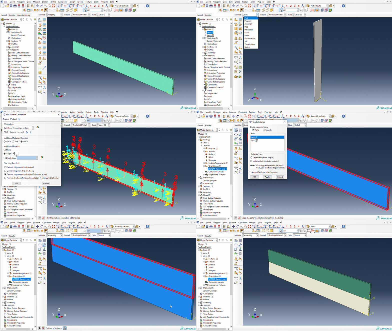
The part representing the 90-oriented layer can be created by simply making a copy of the 0-layer part before modifying the orientation accordingly. Then, append the two parts to the assembly and move the 0-oriented layer to its proper position:
The cohesive interaction is a surface-to-surface contact with the option small sliding and default Cohesive Behavior added to the mechanical contact interaction properties.
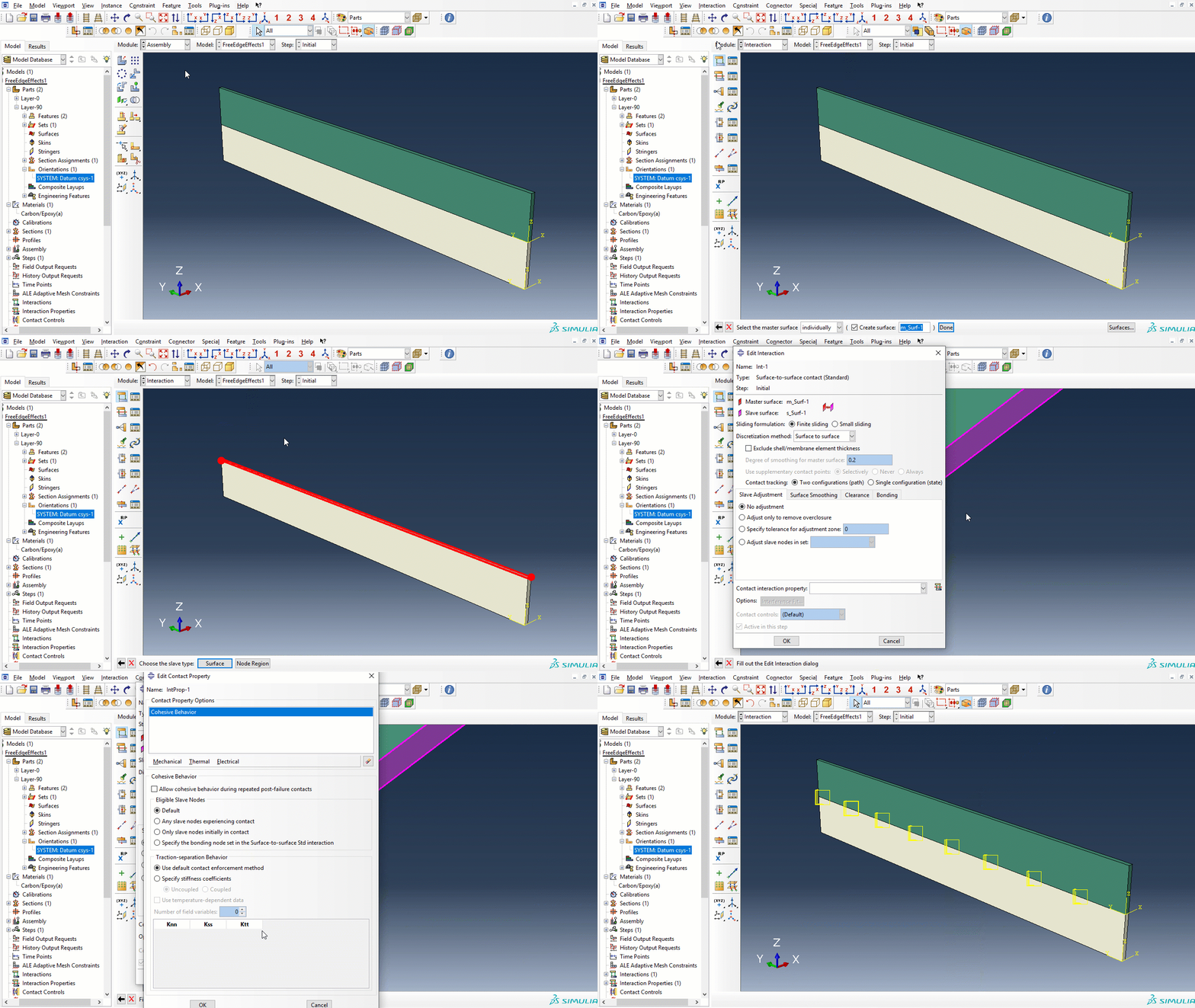
You should generally chose master-slave pairs carefully such that the master surface is the stiffer of the two. For the current case, it does not matter.
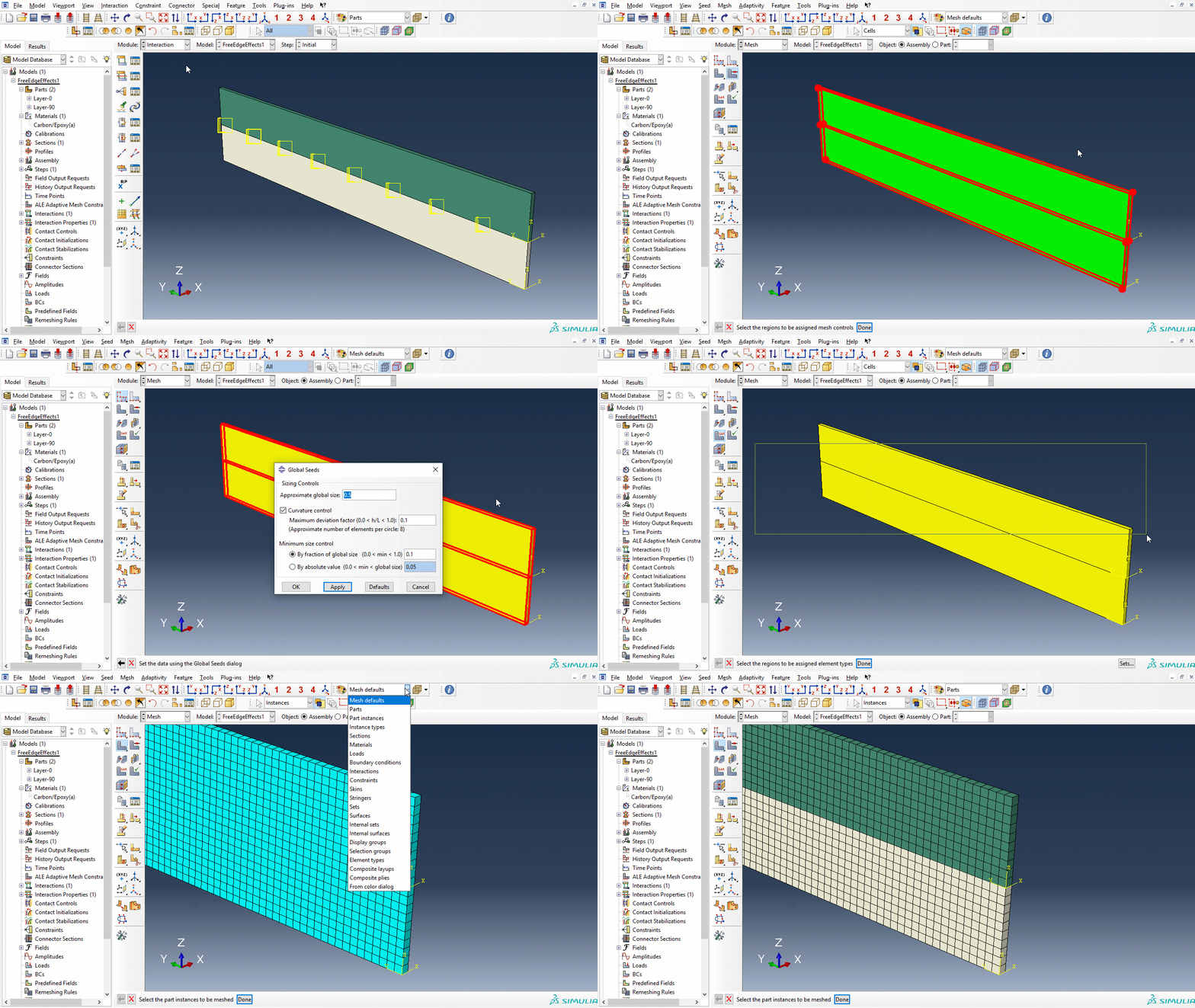
Key parameters for the mesh:
- Element type: C3D8R
- Global element size: 0.1
- Mesh controls: HEX, Sweep
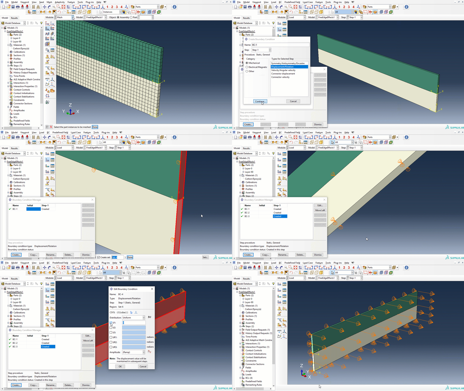
The boundary conditions for the static step are:
- BC-1: On one of the y-z cross section surfaces: $u_x$ = 0
- BC-2: Symmetry condition for the x-z plane: $u_y$ = 0
- BC-3: Symmetry condition for the x-y plane: $u_z$ = 0
- BC-4: Imposed laminate strain $\varepsilon_x^0$ given by $u_x$ = 0.0004.
Computing the layer stresses according to the laminate theory:
import matlib, laminatelib
m = matlib.get('Carbon/Epoxy(a)')

dx = 0.1
ux = 0.0004
strainx = ux/dx

layup=[{'mat':m, 'ori': 0, 'thi':1},
       {'mat':m, 'ori':90, 'thi':1},
       {'mat':m, 'ori':90, 'thi':1},
       {'mat':m, 'ori': 0, 'thi':1} ]

ABD=laminatelib.laminateStiffnessMatrix(layup)
loads,deformations = laminatelib.solveLaminateLoadCase(ABD,ex=strainx)
layres=laminatelib.layerResults(layup,deformations)
print('0-layer stresses(material system) :', layres[0]['stress']['123']['bot'])
print('90-layer stresses(material system):', layres[1]['stress']['123']['bot'])
The transverse stress $\sigma_2$ for the 90-oriented layer is now close to 40 MPa, which is the strength of this material (and the reason for choosing the value of 0.0004 for the imposed displacement in the first place)
Job and results:
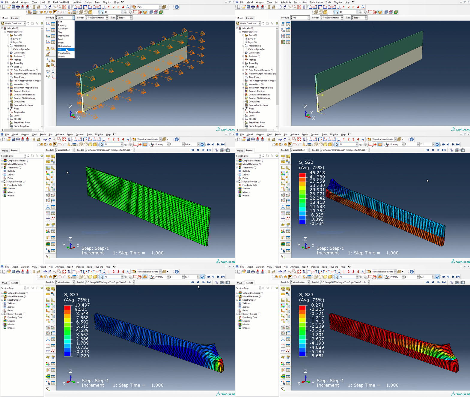
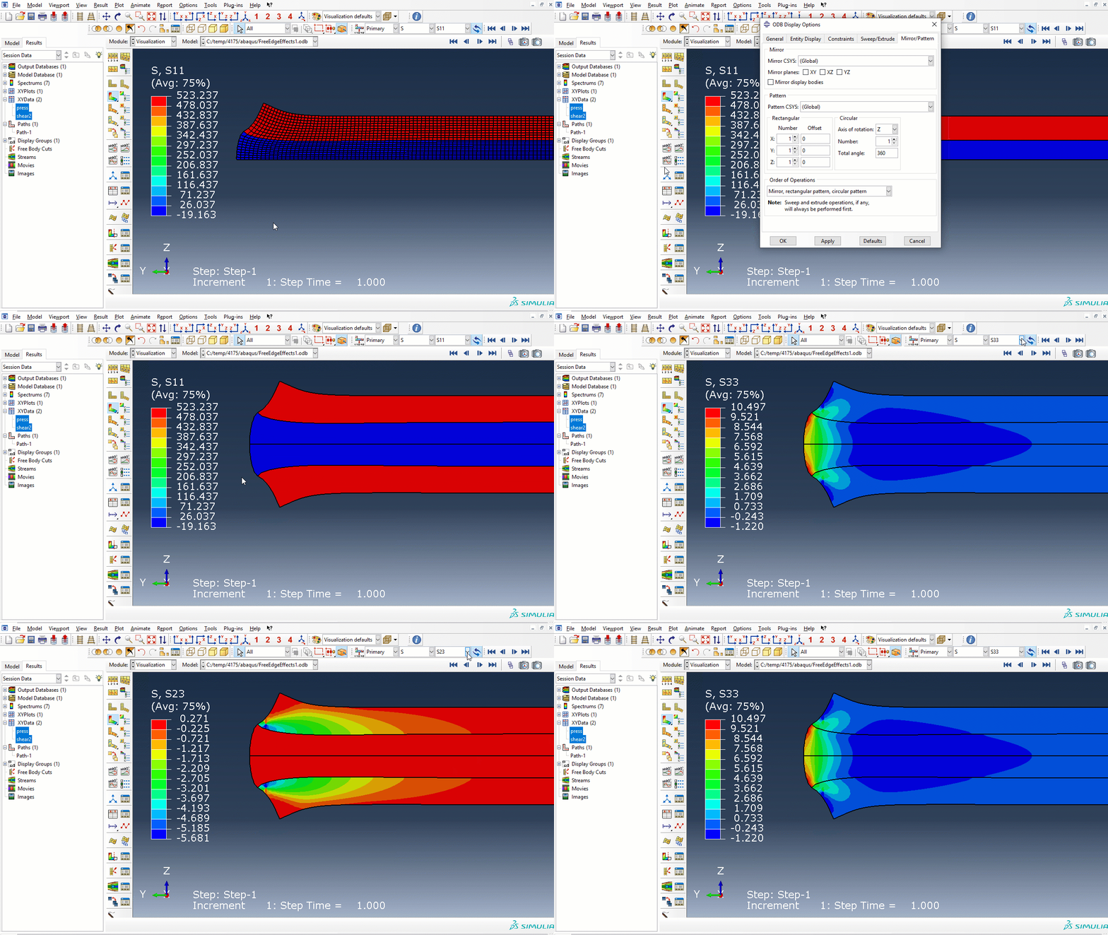
Remember: By default, Abaqus/CAE displays element-based field output results in the coordinate systems defined during preprocessing (the orientation).
The transverse stress (S22) far from the free edge is approximately 40 MPa, and consistent with the laminate theory, while the out-of-plane normal stress (S33) at the free edge is slightly above 10 MPa.
Reporting the interlaminar shear stress, (contact shear stress CSHEAR2) and interlaminar normal stress (contact pressure CPRESS) between the layers using Path and XYData:
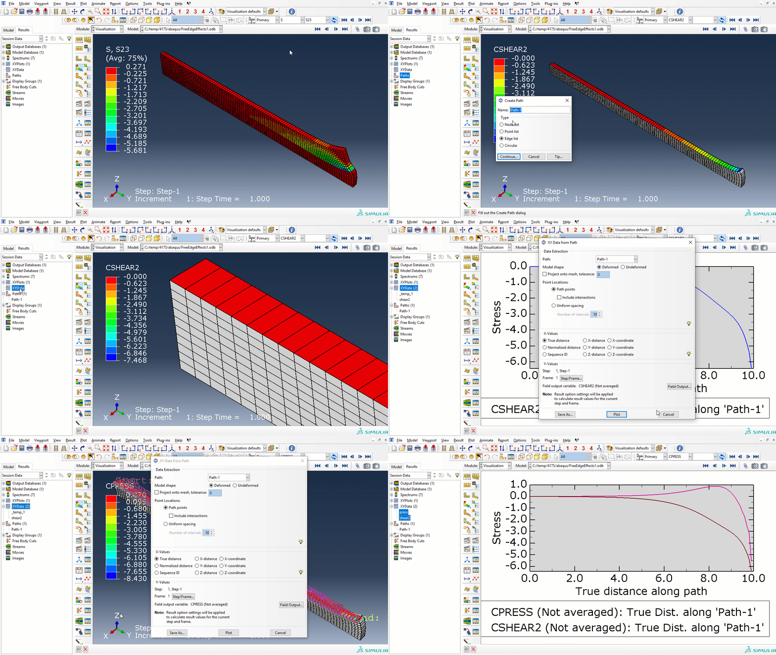
Note that the normal contact stress is defined as pressure, implying that a negativ value of CPRESS represent a tensile stress.
Some additional postprocessing tips:
Disclaimer:This site is about polymer composites, designed for educational purposes. Consumption and use of any sort & kind is solely at your own risk.
Fair use: I spent some time making all the pages, and even the figures and illustrations are my own creations. Obviously, you may steal whatever you find useful here, but please show decency and give some acknowledgment if or when copying. Thanks! Contact me: nils.p.vedvik@ntnu.no www.ntnu.edu/employees/nils.p.vedvik
Copyright 2021, All right reserved, I guess.