In planning of dams it is important to determine the capacity of the spillway. This is useful for the normal operation of the dam and also for safety reasons, in case of floods. There exist design guidelines for spillways which can be applied for simpler flow situations. The design guidelines are made for standard geometries, which are fairly simple. For more complex geometries, a physical model study is needed. Most of the larger dams have a complex geometry, and therefore physical models have been used extensively. The disadvantages with the physical models are high costs and that it can take fairly long time to get the results.
This study describes a numerical model that calculates the water flow over a spillway is modeled numerically in three dimensions. The model includes determination of the free surface. The location of the surface is used to calculate the capacity and the coefficient of discharge for the spillway.
The numerical model solves the Reynolds-averaged Navier-Stokes equations in three dimensions, using the k-epsilon turbulence model. An initial guess is given for the free surface. This is modified by the numerical model using continuity for the cells close to the water surface. After a number of iterations, a steady state solution emerges. The resulting water surface profile is compared with standard formulas for coefficient of discharge for a two-dimensional width-averaged spillway. The coefficient of discharge is calculated with an error of 1.4 % for the two-dimensional case.
The control volume method is used for discretization together with the Power Law Scheme, which is a first-order upstream method. An implicit method is used for time integration. The SIMPLE method is used for the pressure coupling for all cells, except the cells closest to the water surface. For these cells, the continuity of water is used to calculate movement of the water surface.
Symmetric boundary conditions are used for all variables at the water surface, except for the turbulent kinetic energy which is set to zero. Symmetric boundary conditions are also used for the outflow boundary. Velocities are specified at the inflow boundary. As the water level moves, the velocities at the inflow and outflow boundary are adjusted to maintain a constant flux.
The movement of the water surface is done after each time step, which means that this is an explicit method. One of the main problems is therefore oscillations in the water levels and in the velocities close to the surface. Several numerical measures are taken to stabilize the solution.
The discretization procedure uses a non-staggered grid, which means that all the variables are calculated in the center of the cell. Given the continuity defect and a certain time step, a vertical surface movement is calculated for each cell bordering the surface. This movement then have to be transferred to the grid lines that borders the cell. Transferring the movement equally to all cells gave some instabilities. These were reduced when transfering more of the movement in the direction of the water flow. This is similar to an upwind technique used to stabilize the solution of flow equations.
Another measure to reduce instabilities is related to the movement of water surface at the most upstream line of the grid. Oscillations in the water level here would cause instabilities downstream in the rest of the geometry. To prevent this, the water level of the most upstream line of the grid is calculated with a standard one-dimensional backwater calculation, starting from the second most upstream grid line. This technique assumes that the water flow is uniform at the upstream part of the geometry, which is most often true in a reservoir.
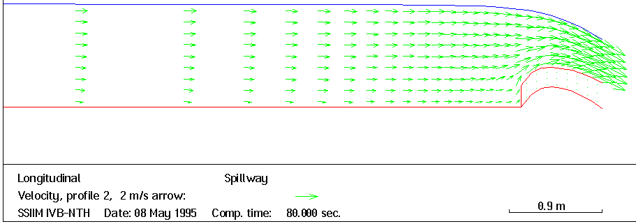
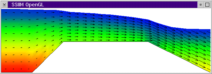
The numerical model is tested on a standard type spillway. A width of 1 meter is used, which gives a two-dimensional width-averaged calculation. The height of the spillway is 0.378 meters, with a design head of H0 = 1.0 m. The grid has 41 and 8 cells in the streamwise and vertical direction, respectively. An upstream discharge of 1 m3/s is specified. Nighter the downstream water discharge nor the location of the water surface is specified. An initial horizontal water surface located 0.75 m above the upstream bed is given. The water surface moves as the calculations proceed. The resulting water surface location and velocity vector field is given in Fig. 1. The upstream water surface is then located at a depth of 0.9602 m. This corresponds to a coefficient of discharge of 1.966. Using standard literature for spillway design the value is found to be 1.946. The two values differ by 1.4 %.
The numerical model is able to predict the coefficient of discharge for the complex spillway used here with an accuracy of 1.4 %. There are some instability problems, which makes it necessary to be careful with the choise of time step and inner iterations.
References: Kjellesvig (1996), Olsen and Kjellesvig (1997)
Longitudinal profile with resulting water surface profile and velocity vectors.
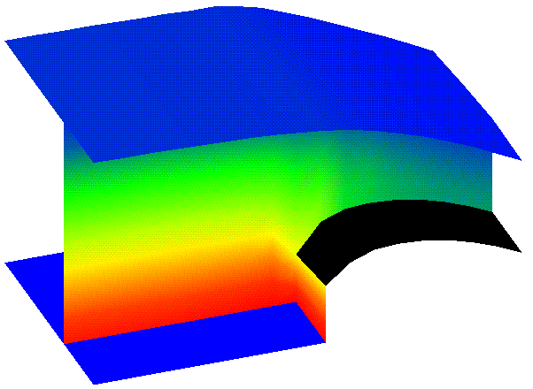
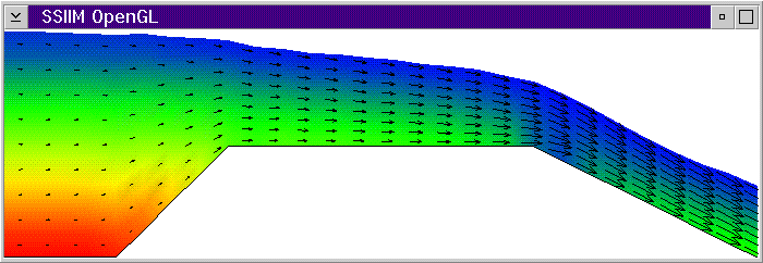
3D view of spillway, showing the bed plane, the water surface and a longitudinal slice. The colors indicate the velocity. The black area is the top of the spillway.

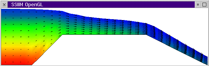
3D view of spillway, showing the bed plane, the water surface and a longitudinal slice. The colors indicate the pressure, except at the horizontal bed which is blue and the spillway which is black.
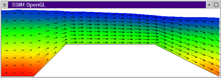
The figures below show the progress of the calculation for a broad-crested spillway.
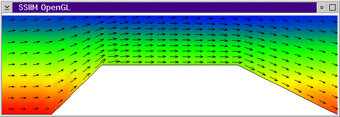
Initial water surface, pressure and velocity field.
After 1 second
After 2 seconds
After 3 seconds
After 25 seconds
This page was last updated: 28 January 1997